


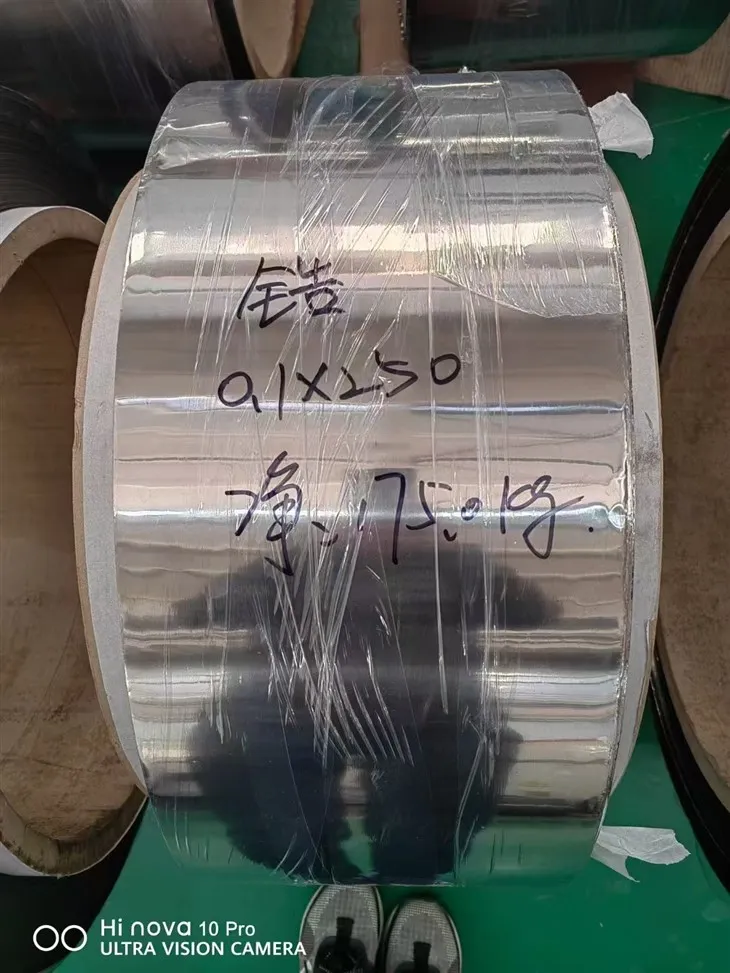


Molybdenum Foil is thin refractory-metal stock used for thermal shields, vacuum-equipment details, electrical components, and precisely cut parts that need a low-mass molybdenum section. It can be supplied as flat pieces, narrow strip, coil, or drawing-shaped blanks. The material is most naturally considered for vacuum or a suitable protective atmosphere, where its refractory character can serve furnace and high-temperature assemblies without treating it as ordinary sheet metal.
At foil thickness, handling and processing condition become central buying issues. A piece can have the correct nominal chemistry yet arrive unsuitable for a close-tolerance stack if thickness distribution, rolling direction, edge damage, surface condition, or transport support has not been addressed. Folding, punching, laser cutting, electrical contact, and thermal cycling each place a different emphasis on the incoming foil. The order should therefore connect material identity and condition to the next operation, specify the useful area rather than appearance alone, and define how flexible pieces will be measured and protected. This approach supports both raw foil orders and cut-part programs without inventing a standard size or universal forming capability.

Material Identity Must Survive the Move to Thin Stock
The word molybdenum does not define a complete composition or delivery condition. State the approved grade, purity basis, or controlled composition and the material document used by the project. If several definitions are acceptable, each offer should identify which one it uses. This matters when foil joins other refractory components or when a previous qualification depends on one material route.
Choose Flat Pieces, Strip, Coil, or Cut Shapes
Flat foil suits manual assembly, shield layers, development work, and cut patterns that need broad access. Strip can reduce conversion work for repeated narrow parts. Coil supports continuous feeding when the production line can handle core, winding, and edge conditions. Drawing-cut blanks move responsibility for outline and holes into the delivered scope, which makes the current revision, datum strategy, and permitted nesting orientation essential.
| Delivery form | Details that define it | Common downstream use |
|---|---|---|
| Flat foil | Thickness, sheet size, usable face, and interleaving | Manual layout or thermal shield fabrication |
| Narrow strip | Width, edge condition, direction, and piece or coil length | Repeated retainers or electrical details |
| Coiled foil | Core constraints, winding, edge protection, and splice policy | Continuous conversion equipment |
| Cut blank | Drawing, profile, holes, burr or cut-edge zones, and marking | Direct placement into a defined assembly |
Nominal thickness, tolerance, width, length, and quantity belong with the selected format. Flexible stock may respond to the pressure of the measuring tool, so the method and sampling locations should be agreed when small differences matter. For cut parts, identify whether dimensions apply before or after any cleaning, flattening, or forming included in the order.
Rolling Direction Shapes the Fabrication Trial
Folds, narrow ligaments, pierced holes, and small-radius corners can initiate damage from an edge or tool mark. A representative trial uses the intended material condition, thickness, orientation, and production tooling. It can answer whether the chosen layout can be handled and formed repeatedly without assuming that results from a thicker molybdenum sheet will transfer directly to foil.
Thermal Shields Depend on Support and Atmosphere
In a furnace or vacuum chamber, molybdenum foil may form a shield layer, liner detail, separator, or flexible thermal component. Describe its support spacing, attachment method, nearby heaters, contact materials, and number of thermal cycles. A wide unsupported area behaves differently from a foil captured around its edge, especially during heating and cooling. Slots, reliefs, overlaps, and attachment holes are part of the thermal assembly design rather than generic material features.
Atmosphere is a decisive boundary. Molybdenum foil is associated with vacuum and controlled protective environments; hot oxygen-bearing exposure requires specific review because oxidation can limit use. Startup, shutdown, cleaning, and maintenance can expose the foil to a different environment from normal operation. Those stages belong in the application description. Where the component needs greater section and rigidity, Molybdenum Plate offers a related thicker form for comparison.

Electrical and Joined Details Need Their Own Surface Logic
A contact area, welded zone, and exposed shield face do not necessarily share the same acceptance needs. Mark functional regions and describe rolling marks, scratches, stains, particles, or other conditions only in relation to their effect on assembly. If cleaning is included, identify the desired process boundary and how the part will be protected afterward. Visual brightness cannot replace a surface requirement connected to electrical contact or joining.
For a slender retainer or tie in the same refractory assembly, Molybdenum Wire offers the related product form.
Measurement Must Account for Flexible Material
Receiving inspection can verify document linkage, thickness, width, length, quantity, orientation, functional surface, and cut geometry. The support condition matters for flatness and profile measurements. A free-hanging sheet, a piece laid on a reference plate, and a restrained shield can produce different observations. If flatness is important to assembly, specify the reference surface, permitted restraint, measurement span, and zone.
| Receiving check | Practical definition | Record retained |
|---|---|---|
| Material link | Grade or purity basis matched to package identity | Certificate-to-lot connection |
| Thickness | Instrument, contact approach, locations, and sample count | Lot dimensional results |
| Functional face | Named zones and relevant visual criteria | Surface acceptance note |
| Cut features | Datum, outline, holes, corners, and edge condition | Drawing inspection report |
| Orientation | Piece or package marking method | Rolling-direction continuity |
Flat Packing Prevents Conversion Loss
Flat pieces benefit from smooth interleaving and rigid sheets that support the entire useful area. Corners should be restrained from sliding without placing a local clamp load on the foil. Coils need a suitable core, protected edges, and restraint that prevents telescoping or crushing. Small blanks can be grouped by part revision and orientation so they remain identifiable after the outer package is opened.
Moisture barriers, sealed wrapping, or a controlled opening environment should be included only when the receiving process calls for them. Inner and outer labels can identify material, thickness, dimensions, quantity, and lot. Permanent marking on a functional foil area is avoided unless the drawing provides a safe location and method.
Questions for Molybdenum Foil Orders
Is thickness and sheet size enough to request a quote?
Add the material basis, condition, delivery form, rolling direction when relevant, functional surface, cut-edge needs, quantity, inspection, and packing. These details determine whether the foil can enter the planned process.
Can molybdenum foil be used hot in ordinary air?
That should not be assumed. The equipment review must consider oxidation across actual temperature, exposure duration, startup, shutdown, and any fault or maintenance condition.
How is rolling direction retained on cut blanks?
The drawing can require a small orientation mark in a nonfunctional area, or the pieces can be packed in a controlled orientation with package-level identification when mixing is prevented.
Can thermal-shield profiles be supplied already cut?
Yes, when the current drawing defines the outline, holes, critical edges, functional face, direction, cleaning scope, and supported packing. Trial parts are useful for delicate features.
What does a meaningful foil flatness check require?
It needs an agreed support surface, permitted restraint, inspection zone, and measurement method. An unsupported visual observation does not describe a repeatable condition.
Assemble the Molybdenum Foil Order
Provide the approved molybdenum identity, material basis, condition, nominal thickness and tolerance, selected sheet or coil format, width, length, quantity, and required cut scope. Add rolling orientation, downstream forming or joining, thermal atmosphere, support arrangement, and any functional surface zones.
Finish the request with measurement and sampling needs, drawing revision, traceability, piece or package marking, cleanliness relevant to the process, and rigid transport protection. The resulting offer can address usable foil and conversion work directly, while the completed thermal or electrical assembly remains tied to its own qualified design.
Hot Tags: Molybdenum Foil, China Molybdenum Foil manufacturers, suppliers, factory, boron and molybdenum, molybdenum alloys, Molybdenum Screw, copper molybdenum, molibden mo, ferro moly price


