

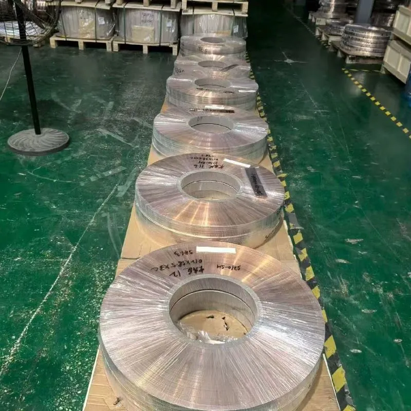
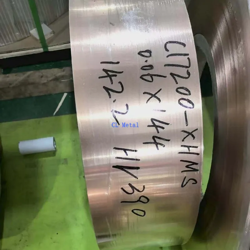
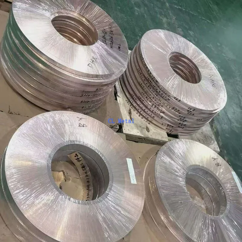
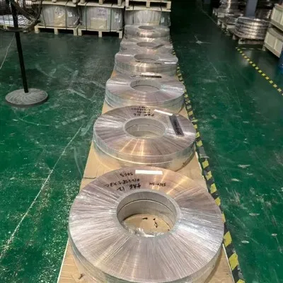
C5191 Phosphor Bronze Foil is thin rolled copper-alloy stock for stamped contacts, resilient clips, shielding details, spring arms, retainers, and compact electrical-mechanical parts. Designers consider it where a component needs a practical combination of conductivity, elastic response, formability, and wear behavior in a thin section. The C5191 designation identifies the intended alloy family, while the controlled drawing or material document still has to define the condition and acceptance basis used by the project. No alloy name alone establishes current capacity, contact life, or forming success.
Foil buying decisions follow the die and the finished function. Temper changes the balance between bend margin and retained spring load. Rolling direction can influence demanding features. Thickness affects punch clearance, part force, and stack height. Slit edge, camber, coil set, surface, and winding determine whether material moves consistently through a feeder. The best order therefore joins material condition to the actual strip layout, critical bends, joining areas, and later plating or cleaning. That connection is more useful than requesting the hardest available foil or the brightest possible surface.
Begin With the Force, Contact, or Shielding Function
A contact spring must carry its designed load while meeting electrical and mating requirements. A retention clip prioritizes grip and dimensional recovery. A shield may emphasize coverage, grounding interfaces, and formed stability. These are different uses even when their stock thickness is similar. Provide the component drawing and identify which function controls material choice.
Current, insertion cycles, temperature exposure, mating wear, soldering or welding, and the operating environment belong to finished-assembly validation. Foil data can support the selected starting condition, but the completed geometry controls local stress and heat. Small coined zones, lances, embosses, sharp transitions, and contact points often matter more than the broad nominal strip.
Temper and Rolling Direction Define the Forming Window
A harder temper may support a higher spring response in a given shape but generally leaves less room for severe local forming. A more formable condition may pass a tight bend while producing different springback and retained load. Neither is automatically superior. The drawing owner should choose from analysis and a trial made with the intended gauge, orientation, and tool sequence.
Show rolling direction relative to spring arms and critical bends when orientation matters. Alternate nesting can improve material utilization, but it may rotate the part into a different forming condition. Qualify both layouts before treating them as equivalent. Test coupons should retain direction identification so reported mechanical results can be interpreted against the actual die feed.
| Part feature | Foil decision it influences | Trial observation |
|---|---|---|
| Spring arm | Temper, direction, thickness consistency | Load, set, and dimensional recovery |
| Tight formed corner | Bend margin and tool-contact surface | Cracking, thinning, and springback |
| Electrical contact zone | Retained face and later finish | Joint or contact behavior after processing |
| Carrier and feed edge | Camber, slit condition, burr direction | Tracking and die stability |
| Plated region | Base surface and cleaning compatibility | Coverage and adhesion in the qualified route |
Usable Gauge Includes More Than Average Thickness
Gauge affects part stiffness, formed height, punch clearance, and stack-up. State the nominal thickness and the tolerance actually supported by the part function. The measurement plan should show where samples are taken across the usable width and along the coil. A narrow average can hide local shape or surface problems that cause more die loss than small gauge variation.
Width, camber, and coil set must suit the feeder and guide arrangement. Define core size, outside envelope, winding direction, and unit mass from the installed decoiler. Large coils reduce changeovers only when the line and lifting equipment can handle them. For pancake coils, cut panels, or short strips, replace broad coil language with support, separation, and flatness details suited to that form.
Retained Edges and Faces Deserve Specific Controls
Slitting can leave burr, rollover, local wave, or sharp corners. Mark the burr side relative to the part and give a practical acceptance rule where the slit edge remains functional. A general demand for no burr can imply secondary work without telling inspection how to release material. Carrier edges removed after stamping can use a different priority from exposed contact or handling edges.
Surface requirements should map to what happens next. Plating, soldering, resistance welding, adhesive bonding, and visible exposure place different demands on incoming foil. Oil state, oxide, pits, pressure marks, and scratches are meaningful only when connected to a retained zone and an inspection method. Visual brightness does not prove solderability, cleanliness, or plating adhesion.

Run the First Coil Through the Intended Production Chain
A representative qualification uses the actual die, lubrication, punch clearance, feed orientation, joining operation, and finishing sequence. Record dimensional yield, cracks, rollover, burr, springback, surface pickup, and the component tests tied to the design. Retain samples with their coil and direction identity if a problem appears. This evidence lets tooling, material, and process variables be separated.
If plating is applied later, incoming foil acceptance and coating acceptance should remain distinct but connected. The base material can be inspected before coating; thickness, coverage, porosity, and adhesion are evaluated in the coating route. Soldered and welded joints need the same division. A material report does not qualify heat input, flux, electrodes, mating metals, or assembly cleanliness.
For a corrosion-focused thin nickel form, compare Nickel Foil. For cell interconnects built around a welding and pack-current decision, use Battery Nickel Strip. These related pages help distinguish product form and use; neither material should replace C5191 from gauge alone.
Coil Protection Starts at the Core
| Handling point | Protective measure | Reason |
|---|---|---|
| Coil center | Sound core sized for the receiving decoiler | Stable support and loading |
| Slit edges | Guards and restraint without edge crushing | Preserves feed and retained edges |
| Functional face | Compatible interleaving where rubbing matters | Limits marks before finishing |
| Lot identity | Core, inner-wrap, and outer-package labels | Connects slit coils to records |
Coil release checks can cover alloy identity, ordered temper evidence, gauge, usable width, camber, edge, surface, and winding arrangement. Store opened material so exposed wraps remain protected from debris and uncontrolled handling. If soldering or plating behavior is sensitive to extended storage, the buyer's quality system defines reinspection rather than assuming transit packaging controls every later condition.
C5191 Foil FAQs
Should I request the hardest temper available?
Only if the formed geometry and trial support it. Higher hardness may change spring load and forming margin, so temper must be selected with bend severity, tool route, and required component response.
Why does rolling direction belong on the layout?
Critical bends and spring elements can respond differently by orientation. Marking direction keeps trial results and production nesting connected to the same material condition.
Can a bright foil surface go directly to plating?
Appearance alone is not a plating preparation. Define the incoming surface, cleaning route, coating process, and coating acceptance separately.
What coil details reduce stamping interruptions?
Specify the core and wound-coil envelope for the decoiler, then add package mass, payout orientation, edge state, camber, and splice policy to suit the feeder and changeover practice.
Give the Die Team a Material It Can Recognize
Order C5191 Phosphor Bronze Foil with the controlled grade basis, temper, thickness, usable width, tolerance priorities, rolling direction, quantity, and supply format. Attach the part layout and identify demanding bends, spring arms, contact zones, retained edges, joining points, and later finishing. Add slit-edge and burr orientation, surface state, coil geometry, inspection methods, lot marking, and protective packing. A first-lot plan should name the component results that matter, allowing repeat material to be judged against a real production baseline rather than a generic alloy description.
Hot Tags: C5191 Phosphor Bronze Foil, China C5191 Phosphor Bronze Foil manufacturers, suppliers, factory, Gr12 Titanium Rod, Gr12titanium Alloy Plate, tio2 anatase, titanium, titanium chains, titanium quartz


